Controlling servomotors in Rust with Micro:bit V2
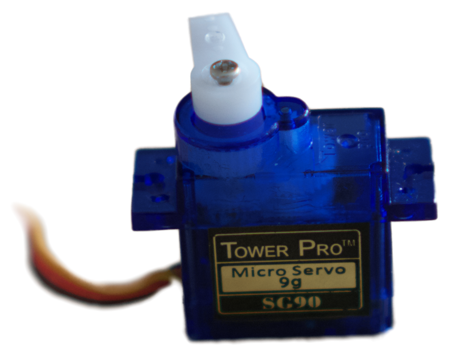
Servomotors are cool devices that can be easily controlled any PWM capable microcontrollers. Today we'll try to control an SG90 (fig. 1) microservo using a Micro:bit and Rust!
How to talk to servos
Servomotors are controlled by using PWM (Pulse Width Modulation) signals. Think about a square signal but with unequal up and down time. The ratio between up and down time is called the duty cycle. A duty cycle can vary between $0$ (always $0$ signal) and 1 (always $1$ signal). A perfect square wave has a duty cycle of $0.5$.
Because a PWM signal is a real voltage signal, we need something to generate it. One way to do it is to use a microcontroller.
The Big Brain
I'll use a Micro:bit board in its V2 version. This cheap hardware has a microcontroller (called the nRF52833) based on Cortex-M4 ARM architecture, and other components such as a speaker, buttons or leds. Really, we'll only use the MCU (microcontroller unit) capabilities for now.
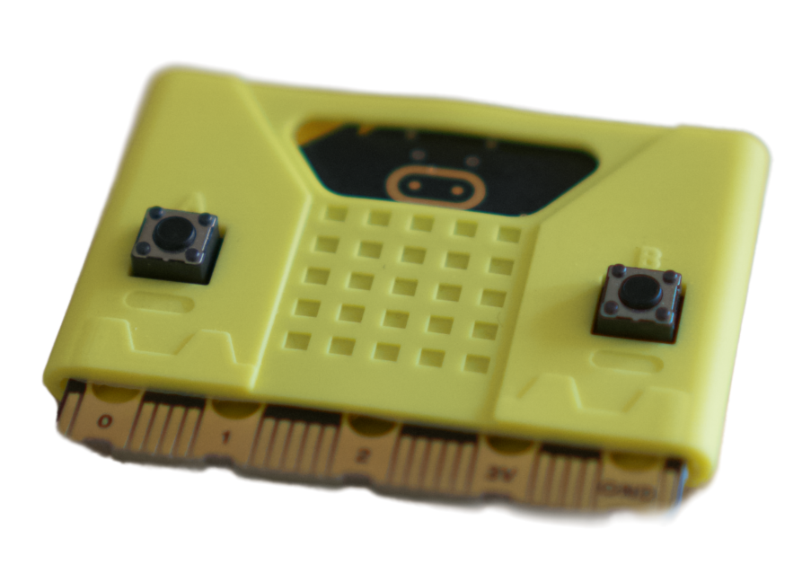
See the bottom pins ? This is where all GPIOs are exposed as well as voltage references such as 3V and GND.
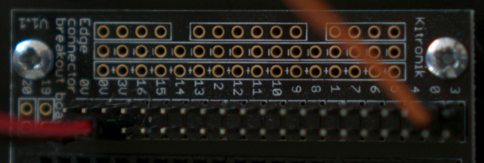
I use a this connector breakbout board in order to access the various pins more easily.
The last thing, but not the least, is to program this thing. While the easy and most used pathway would be to use C++ libraries here, I decided to learn bits of embedded programming in Rust.
Programming the yellow thingy
There is a great resource out there for beginners which is the Discovery book. Its author goes from the setup instructions to various peripheral programming and is a really nice introduction to embedded rust, can't recommend it enough if you want to dive into this kind of things.
Unfortunately, the PWM peripheral is not covered in this book. So we'll have to use the specific abstractions of the nfr52833 rust crate! Really, this is where the fun begins.
There are a lot of HAL (Hardware Abstraction Layer) crates developed by the rust community for many microcontrollers (built on top of micro-architecture crates and peripheral access crates). The micro:bit also has the highest level of abstraction crate available, which is a board crate.
Ideally, one should only use board or HAL crates for any classical use. The great thing about embedded-HAL is that the API defines common traits that are later implemented in device specific HAL crates (including the one for our chip). This means that your code work on others microcontrollers if they have the same capabilities!
PWM, come at me
There are (no) few resources on this topic (enabling the PWM peripheral for micro:bit with Rust), because it's still relatively new and niche. Our best choice here is to get into the code and read comments. Below, I will describe step by step the code used to control our servo motor.
#![no_main]
#![no_std]
Hey, we are in embedded territory here, forget your println.
use rtt_target::{rprintln, rtt_init_print};
use panic_rtt_target as _;
Here we import the RTT (Real Time Transfer) I/O protocol functions that will allow use to print (actually rprint) variables living on the device via USB.
use microbit::hal::{pac::Peripherals, gpio, pwm, gpio::Level};
use microbit::hal::prelude::*;
Then, each lib from the HAL that we may use is imported, including pwm.
#[entry]
fn main() -> ! {
    rtt_init_print!();
Here we set the attribute #[entry] for our main() function in order to tell the MCU that this function is our entrypoint for the program execution.
Then, the RTT communication is initialized.
// Get ownership of peripherals
let board = Peripherals::take().expect("Couldn't initialize board.");
First, we get the ownership of all the HAL peripherals. We will use it to access pins and PWM peripherals.
// Configuring output pin
let gpio = gpio::p0::Parts::new(board.P0);
let pwm_pin = gpio.p0_02.into_push_pull_output(Level::Low).degrade();
Then, we declare the GPIO pin we want to use for the PWM signal. I will use the pin $0$ here, which, according to this reference is connected to the GPIO P0.02 on the nRF52833. I then make the pin a push_pull output and degrade() into a generic Pin struct expected by later code.
let pwm_motor = pwm::Pwm::new(board.PWM0);
pwm_motor.set_output_pin(pwm::Channel::C0, pwm_pin);
This is where the magic happens. We define our variable pwm_motor by creating a new Pwm struct from the board PWM peripheral board.PWM0. Then, we set the output pin created earlier.
pwm_motor.set_prescaler(pwm::Prescaler::Div32);
pwm_motor.set_max_duty(10_000_u16);
The prescaler part and max duty cycle here is worth going through: when I was searching how to set a given period to my signal, I read this code inside hal's pwm.rs.
pub fn period(&self) -> Hertz {
    let max_duty = self.max_duty() as u32;
    let freq = match self.prescaler() {
        Prescaler::Div1 => 16_000_000u32 / max_duty,
        Prescaler::Div2 => 8_000_000u32 / max_duty,
        Prescaler::Div4 => 4_000_000u32 / max_duty,
        Prescaler::Div8 => 2_000_000u32 / max_duty,
        Prescaler::Div16 => 1_000_000u32 / max_duty,
        Prescaler::Div32 => 500_000u32 / max_duty,
        Prescaler::Div64 => 250_000u32 / max_duty,
        Prescaler::Div128 => 125_000u32 / max_duty,
    };
    match self.counter_mode() {
        CounterMode::Up => freq.hz(),
        CounterMode::UpAndDown => (freq / 2).hz(),
    }
}
Following this code, I made sure to set my prescaler division and max_duty right. According to the SG90 datasheet, the expected frequency is $50 \text{Hz}$. I saw that 500_000u32 was an available prescaler value and I just needed to set max_duty to 10_000_u16 in order to get a frequency of $50 \text{Hz}$.
pwm_motor.loop_inf();
Then I make the pwm loop for ever.
let mut duty = 650_u16;
pwm_motor.set_duty_off(pwm::Channel::C0, duty);
At last, I send the duty variable to anything between 200 and 1200 to span the whole range of acceptable duty cycle accepted by my servo motor (the values are close to the 1ms and 2ms displayed on the datasheet, but I found those lasts to better match the whole angular span of my motor).
Do not forget the empty loop loop{} at the end in order to force the program to run indefinitely.
Flashing the MCU
Once setup, the compilation of the program (pwm.rs) and its flashing on the device is straight forward:
cargo embed --features v2 --target thumbv7em-none-eabihf --bin pwm
If no error are raised, your program is probably running right now!
Is it moving now?
Before connecting anything to the actual motor, I checked with my oscilloscope if the generated signal was indeed what I thought it was. Connecting the output pin 0 to my probe, I measured the duty cycle and frequency and validated my program.
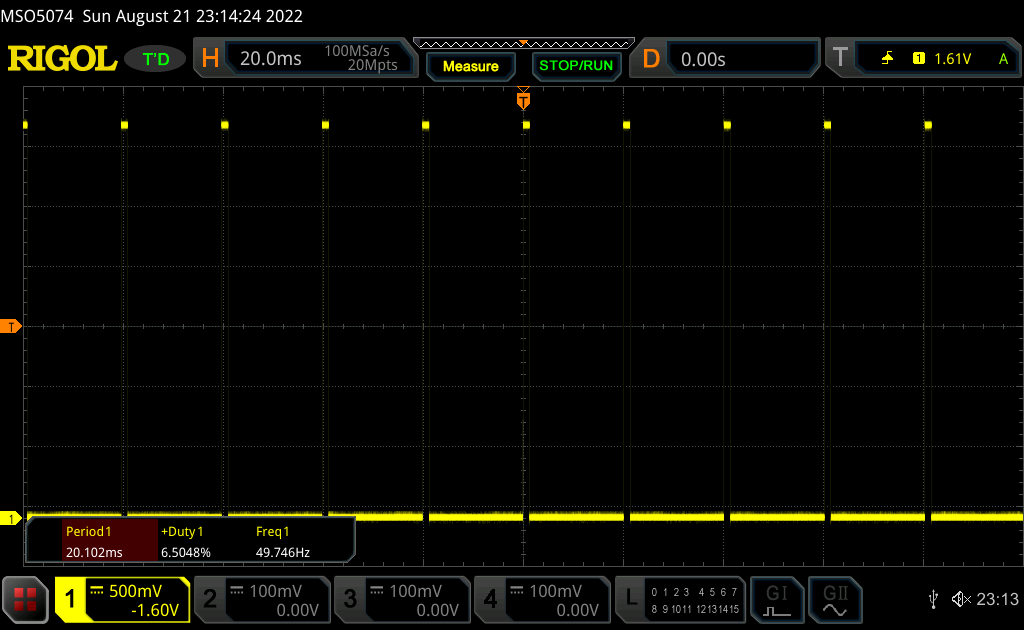
I read a frequency value around $49.7 \text{Hz}$ and a duty cycle of roughly $6.5$%, which matches with my input duty_cycle variable of 650_u16 (650_u16 / 10_000_u16).
The value 650_u16 is not coming from nowhere, I figured it was the noon position of my motor. Let's try to move it all the way to one side by setting the duty_cycle to 200_u16.
And all the way to the left ? duty_cycle to 1200_u16.
Perfect, it's working as expected! I hope you enjoyed this small walk-through as much as I did when experimenting. I published the whole repository if you would like to try at home, feel free to fork it and make it your own.
See you later!